Dear Jeff Thornton
I would like to ask you if there is a type in TRNSYS wich simulate an MCP (material phase change) model
thank you
Kaouther Ben Nasr
Docteur Ingénieur\\Génie Énergétique
Maître assistant à l'ENAU
Chercheur au CRTEn\\Technopôle Borj Cédria
mobile: +216 53 48 44 38
Docteur Ingénieur\\Génie Énergétique
Maître assistant à l'ENAU
Chercheur au CRTEn\\Technopôle Borj Cédria
mobile: +216 53 48 44 38
De: "Jeff Thornton via TRNSYS-users" <trnsys-users@lists.onebuilding.org>
À: "Amirreza Heidary" <amirrezaheidarysbu@gmail.com>, "TRNSYS users mailing list at OneBuilding.org" <trnsys-users@lists.onebuilding.org>
Envoyé: Samedi 29 Avril 2017 16:52:42
Objet: Re: [TRNSYS-users] problem with differential controller
On Apr 29, 2017, at 2:36 AM, Amirreza Heidary via TRNSYS-users <trnsys-users@lists.onebuilding.org> wrote:
_______________________________________________
TRNSYS-users mailing list
TRNSYS-users@lists.onebuilding.org
http://lists.onebuilding.org/listinfo.cgi/trnsys-users-onebuilding.org
À: "Amirreza Heidary" <amirrezaheidarysbu@gmail.com>, "TRNSYS users mailing list at OneBuilding.org" <trnsys-users@lists.onebuilding.org>
Envoyé: Samedi 29 Avril 2017 16:52:42
Objet: Re: [TRNSYS-users] problem with differential controller
Amirreza,
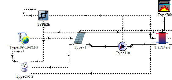
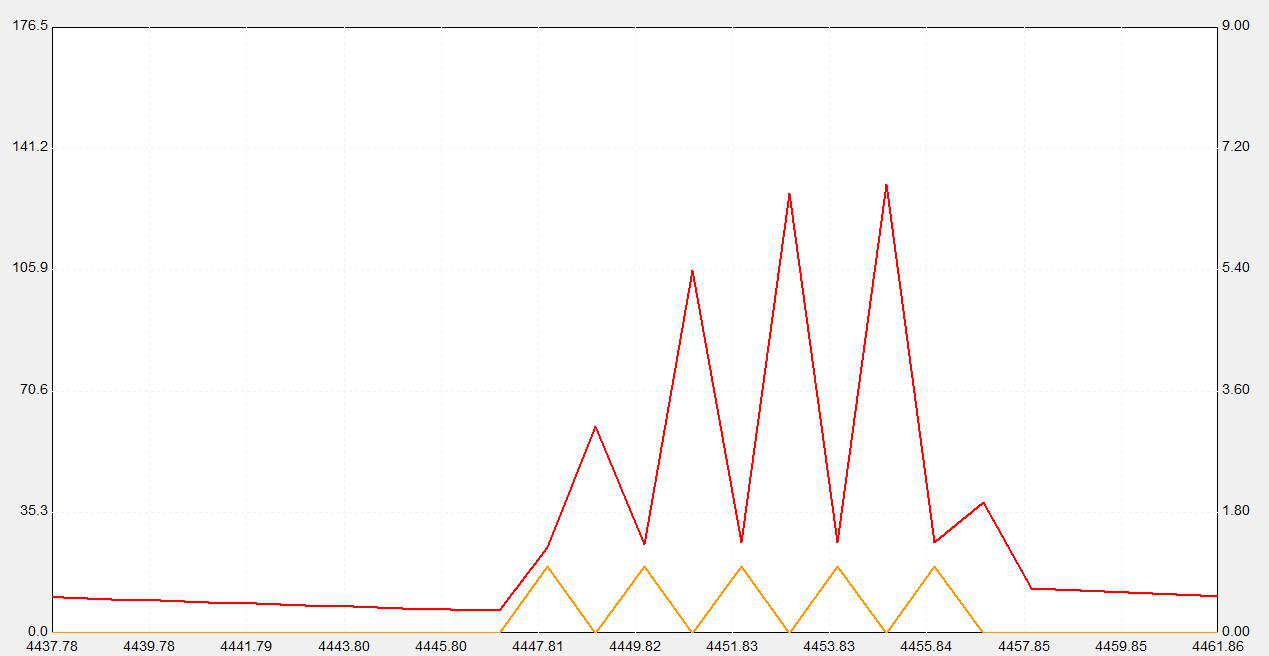
Real solar collectors do the same thing under certain circumstances. From a first glance I would say your dead bands are too tight - typically we see 10/2 not 5/2. It's also possible that your collector pump flow rate is too high. With collectors connected in series you typically have a pump flow rate the same as if you had only one collector. Collectors are designed for a given maximum flow rate for pressure drop reasons. For example, assume we had a collector that wanted 450 kg/h of flow and we had 6 in series. We would run the pump at 450 (each collector gets the 450 that way). You wouldn't run your pump at 2700 (450 x 6) or the pressure drop would be ridiculously high. If you have that high of a flow rate you'll get exactly what you are seeing in your project. With no flow the collector temperature is above the deadband but when the pump turns on the high flow rate causes the outlet temperature to drop below the lower deadband. The controller can't find a solution since both are correct and will oscillate between on and off.
Jeff
TESS Inc
Sent from my iPhone
On Apr 29, 2017, at 2:36 AM, Amirreza Heidary via TRNSYS-users <trnsys-users@lists.onebuilding.org> wrote:
Dear All
I'm using a 5 collectors in series with a differential controller to turn on the pump when the difference of collector outlet and inlet temperatures is more than 5 and turn it off when it is less than 2.But the signal and collector output temperatures are fluctuating too much, also the signal is not compatible with temperature variations.as you can see in the following diagram, the signal is 1 when the outlet temperature is at maximum !(red line is collector outlet temperature and orange line is the controller signal) --------------------------------------------------------------------------------------------------------------------------------------------------amirrezaheidarymaster student of energy systems EngineeringSharif university of technologyTehran-IranE-mail address:P Save a tree... Please don't print this E-mail unless you really need to.
_______________________________________________
TRNSYS-users mailing list
TRNSYS-users@lists.onebuilding.org
http://lists.onebuilding.org/listinfo.cgi/trnsys-users-onebuilding.org
_______________________________________________
TRNSYS-users mailing list
TRNSYS-users@lists.onebuilding.org
http://lists.onebuilding.org/listinfo.cgi/trnsys-users-onebuilding.org
