Hello,
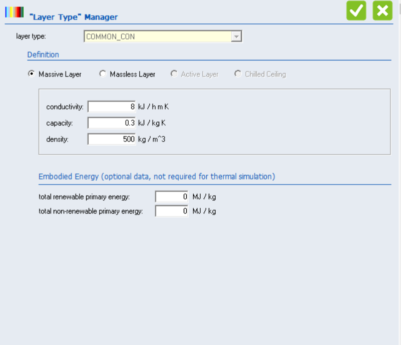
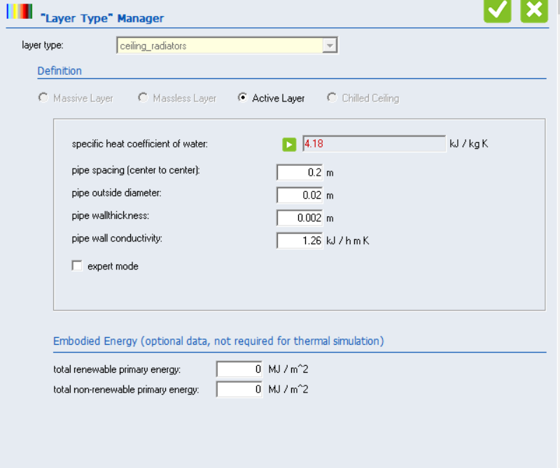
I am trying to model a ceiling heating system in type 56b. The actual heating system is actually some hot water heating panels that are located in the ceiling. The actual sizes or thickness of layers are not important, and I only expect the model to reflect a realistic behavior. To model the ceiling heating system, I putted an active layer between two layers of common concrete. The specifications of active layer, common concrete, and the ceiling structure are shown below. However, the model does not show a reasonable behavior because:
1- The temperature increment of the zone is very small (with 11000 L/H flowrate and 26 C inlet water for a 50 m2 zone)
2- The temperature increment of zone does not change with the change of inlet flowrate
3- When I change the specifications of active layer (for example by reducing the pipe spacing), the minimum required flowrate of water reaches to unreasonable high values
I tried to get a reasonable behavior by trying following actions:
1- Reducing the thermal capacity of common cement: It did not work because when I have a big surface with very low thermal capacity, the solar radiation from windows increases the zone temperature to very high values (e.g. 30 C). The same happens with the use of low-capacitance layers like hollow brick.
2- Trying the chilled ceiling: Although it is not exactly what I need, I tried it to see if it can have a reasonable behavior. But it does not do any change of indoor air temperature (maybe it is only coded for cooling!)
3- Huge increase in inlet flowrate: Does not change anything !!!
I have attached the .b18 file as well. The inlet temperature and flow to the active layers are as inputs (from other components). The simulation timestep is 30 minuts. Would you please let me know why the zone temperature variation versus the inlet water temperature is extremely low and how I can fix it?


