[Date Prev][Date Next][Thread Prev][Thread Next][Date Index][Thread Index]

[TRNSYS-users] PROBLEM WITH LARGE OPENING IN TRNFLOW


Greetings to everybody,
I tried to understand how TRNFLOW works starting from the study of the sample model available in TRNSYS software.

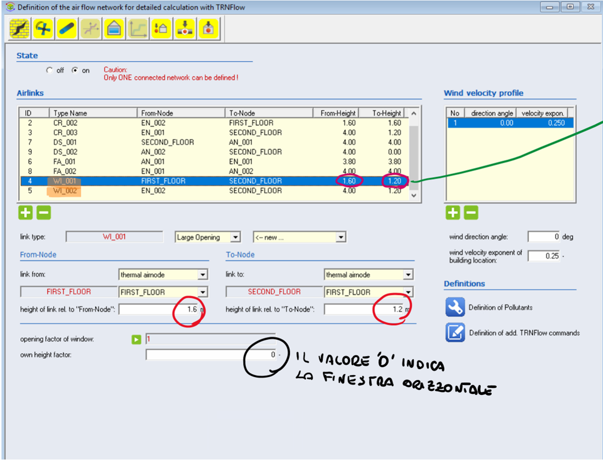
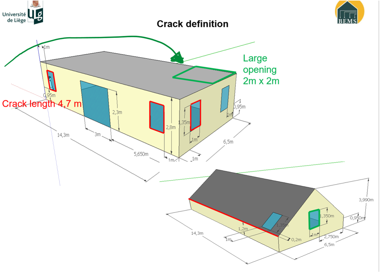
One of the main problems I encountered was to understand the reference heights shown in Figure 1 circled in red. The line highlighted in orange with the initials "WI_" (Figure 1) indicate the type of connection "large opening" which correspond to the openings in green in Figure 2, which in this case represents a "hole in the floor".

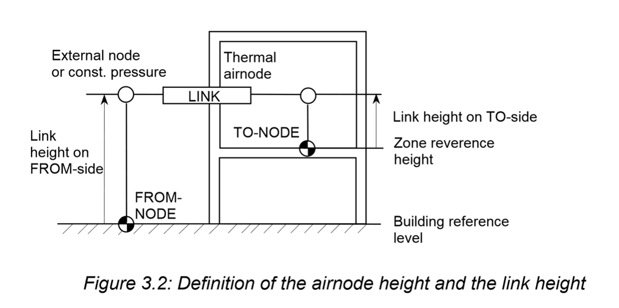
I cannot, therefore, understand which distances are indicated as FROM-NODE and TO-NODE. (1.6 and 1.2 in the example). I have reported the text of the guide above Figure 3 which refers precisely to these distances. I, therefore, write to you asking if you can kindly help me understand how to interpret the heights indicated above. 
Best regards


응ⅡIll喜 
:로昌들昌= 
=§|터터타들뎧 
-돈뗨넣g궆궆  con annotazioni a penna con annotazioni a penna

 Figura 1  

n i versiti 
Crack definition 
Large 
opening 
2m x 2m 
--00, 2m


Figura 2


Here the link height on the side of the “From-Node” (“To-Node”) has to be defined. This height is measured from different levels depending on the selected node and its category: If it is an external node or a constant pressure node the link height is measured from the building reference level. In thermal airnodes and auxiliary nodes the link height is measured from the corresponding node reference height which is defined in the node data (see figure 3.2). For a large opening the link height is measured to the bottom of the opening. With different absolute heights on the from and the to side a link is not horizontal that means the link itself acts as a vertical shaft. This is possible  with all link types except with large openings.
 

External node 
or const. pressure 
Thermal 
airnode 
Link 
height on 
FROM-s•ide 
LINK 
Link height on TO-side 
TO-NODE 
Zone reverence 
height 
FRO M - 
NODE 
Building reference 
level 
Figure 3.2: Definition of the airnode height and the link height

                                          Figura 3

--
Logo Unical

Domenico Mazzeo (Ingegnere Energetico) 
Ph.D. Ing. Domenico Mazzeo
Dipartimento di Ingegneria Meccanica, Energetica e Gestionale - DIMEG
Università della Calabria
Via Pietro Bucci, 44C
87036 Rende (CS) Italy
e-mail: domenico.mazzeo@unical.it 
 Skype: domenicomazzeo87

PNG image