[Date Prev][Date Next][Thread Prev][Thread Next][Date Index][Thread Index]

Re: [TRNSYS-users] Energy losses on solar collector's heat exchanger before the loop starts


Javier,

It might help to send the printers, integrators and output devices to a hidden layer so we can see your project a bit more clearly, but I do have one question.  Are you using the outputs of the solar collectors to set the flow rates in their respective loops?  Both 538 and 539 will calculate the required flow rate to meet the desired outlet temperature.  This flow rate will need to be identical throughout that loop (pumps, tanks etc.).  Double check that first.  Otherwise I may suggest that you remove the capacitance from the collector and add a few pipes in each loop.  There are times that the control algorithms will deliver strange-looking results with collectors with mass. 

The ideal way to handle this situation is to have a control collector (a collector that sees the same inlet temperature, ambient temperature and solar radiation but has no mass).  This control collector is then used to set the flow rate for the real loop which contains the collectors with mass.  We use that approach routinely and with good results.


Jeff


---
Jeff Thornton President - TESS LLC 22 N. Carroll Street, Madison WI USA 53703 Office: (608) 274-2577 Fax: (608) 278-1475 www.tess-inc.com E-Mail: thornton@tess-inc.com

On 12/13/2016 2:21 pm, Javier Vega via TRNSYS-users wrote:

Hello TRNSYS community,
 
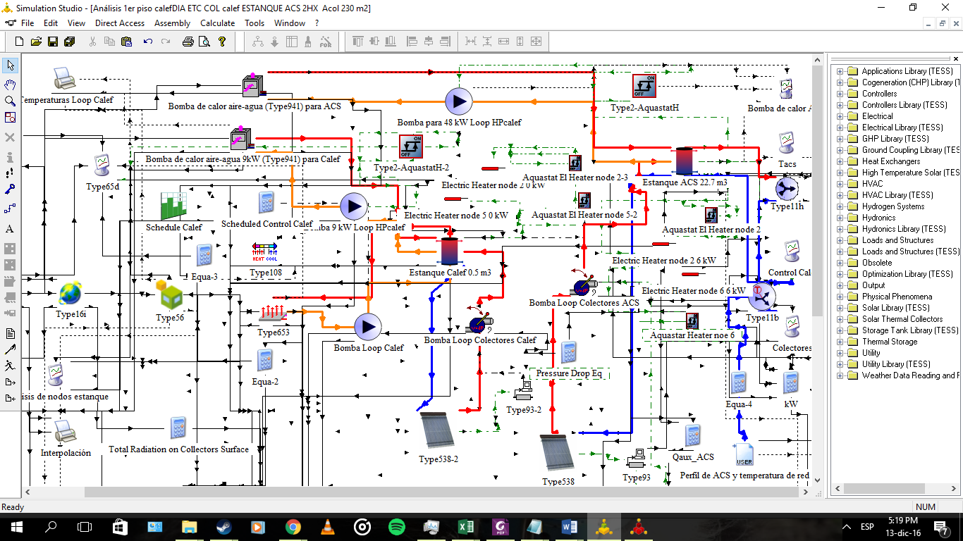
I'm using Type 538 and 539 to model ETC and Flat Plate collectors. I have them connected to Type 695 (variable speed pump) and a HX in a solar water tank modeled through Type 543 (Coiled). In the tank, there is also another HX connected to a Heat Pump water loop.
 
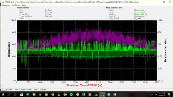
I'm using Type 538 and Type 539 in Control Mode 4, meaning the solar collector loop works only if the fluid can win energy. But, nevertheless, everytime the solar collectors activate and start to supply energy, I get negative power peaks. I've noticed the same occurs sometimes with the heat pump's heat exchanger, but just a few times.
 
I haven't calculated the impact of this phenomenon in my whole simulation. Anyway, should I really expect this results in my calculations? Maybe it's the effect of the capacitance of the collectors array.
 
I will attach some images that may help. The units are in kW and the info shown in the plot correspond to the energy transfer rate in the Heat Exchangers.
 
Imágenes integradas 1
 
Imágenes integradas 2
 
Thanks in advance, greets from
Javier Vega Benavente
Mechanical Engineering Student, Universidad de Concepción, Chile


_______________________________________________
TRNSYS-users mailing list
TRNSYS-users@lists.onebuilding.org
http://lists.onebuilding.org/listinfo.cgi/trnsys-users-onebuilding.org

PNG image