Thanks a lot for your helpful answer!
I got the airflow part right.
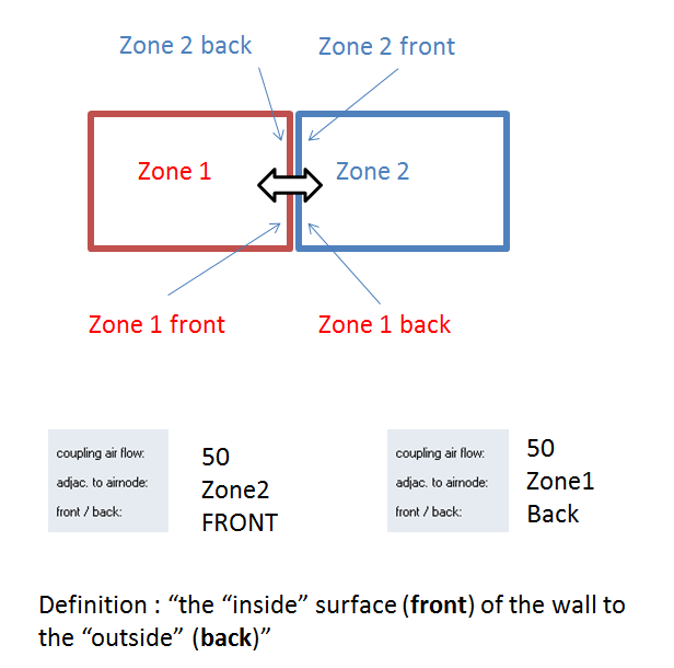
However, the front/back issue is not clear to me and I could not find an explanation in the documentation.
Please have a look at the following sketch:
- is this the correct setting?

Sorry for the probably easy question, but at least for me it is not totally clear how to define it.
Thanks a lot!!
Philip
On 7/25/2014 9:38 PM, David BRADLEY
wrote:
Philip,
When you define a coupling air flow rate through an ADJACENT wall, a quantity of air from the ADJACENT zone enters the active zone. In your first picture below, 90 kg/h of air would enter zone AT_109 from airnode R_107. If you click on the little green arrow button that allows you to set whether the flow is constant, scheduled, or an input, you will see a note explaining what the conditions of the air entering the zone will be. If you want air to flow the other direction as well (from AT_109 to R_107) you have to define that separately in zone R_107.
The front/back switch has to do with the thermal model and which surface of the wall is in a given zone.
Kind regards,
David
On 7/25/2014 08:05, Philip wrote:
Dear All,
I could not find an explanation on the coupling "front/back", see below.
I want to model an inter-zonal airchange between 2 zones (AT_009 and R_007- green arrow in the screenshot), so I have to define one zone as "front" and one as "back" and define the same coupling rate in both zones.
- But does it make any difference which is defined as front and which as back?
There is also a TRNFLOW Network that connects some other zones (AT_009 and AT_109 etc. ..) in order to realize night ventilation through an Atrium.
The zone R_007 is not connected to the TRNFLOW network, but I guess it would make sense to link it?
Any help highly appreciated!!!
Thanks, and have a nice weekend,
Philip